Department Microstructure and Residual Stress Analysis
Sample environment
The E3 is capable to use environment such as furnaces and cryostats provided and services by the HZB sample environment group. If you plan to use such devices for your measurement, mention that in your beamtime proposal and/or contact us. However, further devices can exclusively be used on E3 to measure your samples.
Sample table / mounting
The E3 sample table consists of an omega circle with an x-y-z stage on top to carry loads of up to 300 kg and to drive them precisely within a range of 250 mm in all three x, y and z directions. We offer a number of mounting adapters to fix samples with a broad range shapes and sizes. If you want to bring your own sample holders and grips please also consider the plates available on E3:
(a) Standard sample table plate
(b) Irelec adapter (e.g. for cryofurnaces)
(c) squared adapter plate
(d) circular adapter plate
Detailed dimensions of the sample plates are provided via the download box.
Goniometer
We further provide an open goniometer tilt stage to mount samples of up to 50 kg and measure three perpendicular strain directions consecutively with one alignment. Optionally, another rotation stage on top of the goniometer can be used to measure extra orientations or let the sample continuously rotate in order to increase grain statistics, for example. Figure 2 demonstrates this setup.
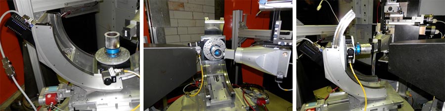
Fig. 2: The goniometer table enables measurements of multiple sample orientations within one setup.
Load frame (tension/compression)
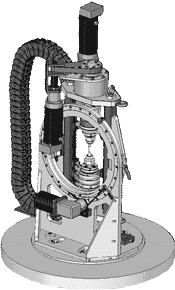
Fig. 1: Tiltable load frame.
Since 2013, a new load frame for tension and compression tests of up to 50 kN load capacity is available on E3. The machine is mounted on a tiltable stage to have access to three perpendicular sample orientations within one alignment[1]. Figure 5 demonstrates this capability. Although, the devices load cell and the available extensometer are controlled by a proprietary measuring and controlling system an interface has been created to use the load frame with the E3 instrument control software CARESS, such that scans against loads and strains are possible.
Various sample grips allow testing samples of different shapes and sizes as shown in figure 6. If you plan to use the load frame during your beamtime, contact us to discuss your sample geometry. Detailed sample holder information is provided by the download box.
Fig. 2: Click picture to watch the frame tilting.
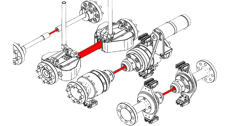
Fig. 3: Available sample grips for the loadframe. To indicate the different geometries the samples are highlighted in red.
Additionally, a shared load frame to also allow for torsion tests is available in collaboration with the HZB neutron radiography& tomography and the University of Tennessee Knoxville (UTK)[2].
References:
[1] Rotatable multifunctional load frames for neutron diffractometers at FRM II - design, specifications and applications, M. Hoelzel et. al. (2013), Nucl. Instrum. Methods Phys. Res., Sect. A 711, 101-105, doi: 10.1016/j.nima.2013.01.049
[2] Neutron Bragg-edge-imaging for strain mapping under in situ tensile loading, R. Woraceket. al. (2011), J. Appl. Phys. 109(9), 093506, doi: 10.1063/1.3582138