Department Undulators
Design & Characterization
One undulator can consist of more than 1000 permanent magnets. Each magnet is characterized with respect to the dipole component and inhomogeneities. The dipole moments are measured in an automated Helmholtz coil and the magnet inhomogeneities are measured in a stretched wire system. The obtained data are used to assign each block to a unique position within the magnetic arrays of an undulator using a sorting technique known as simulated annealing. The data are used in a sorting code based on a simulated annealing algorithm. A precise assembly permits guarantees an accurate prediction of field errors of the complete device without further iterations. The quality of an unsorted magnet configuration is one order of magnitude worse as compared to a sorted configuration.
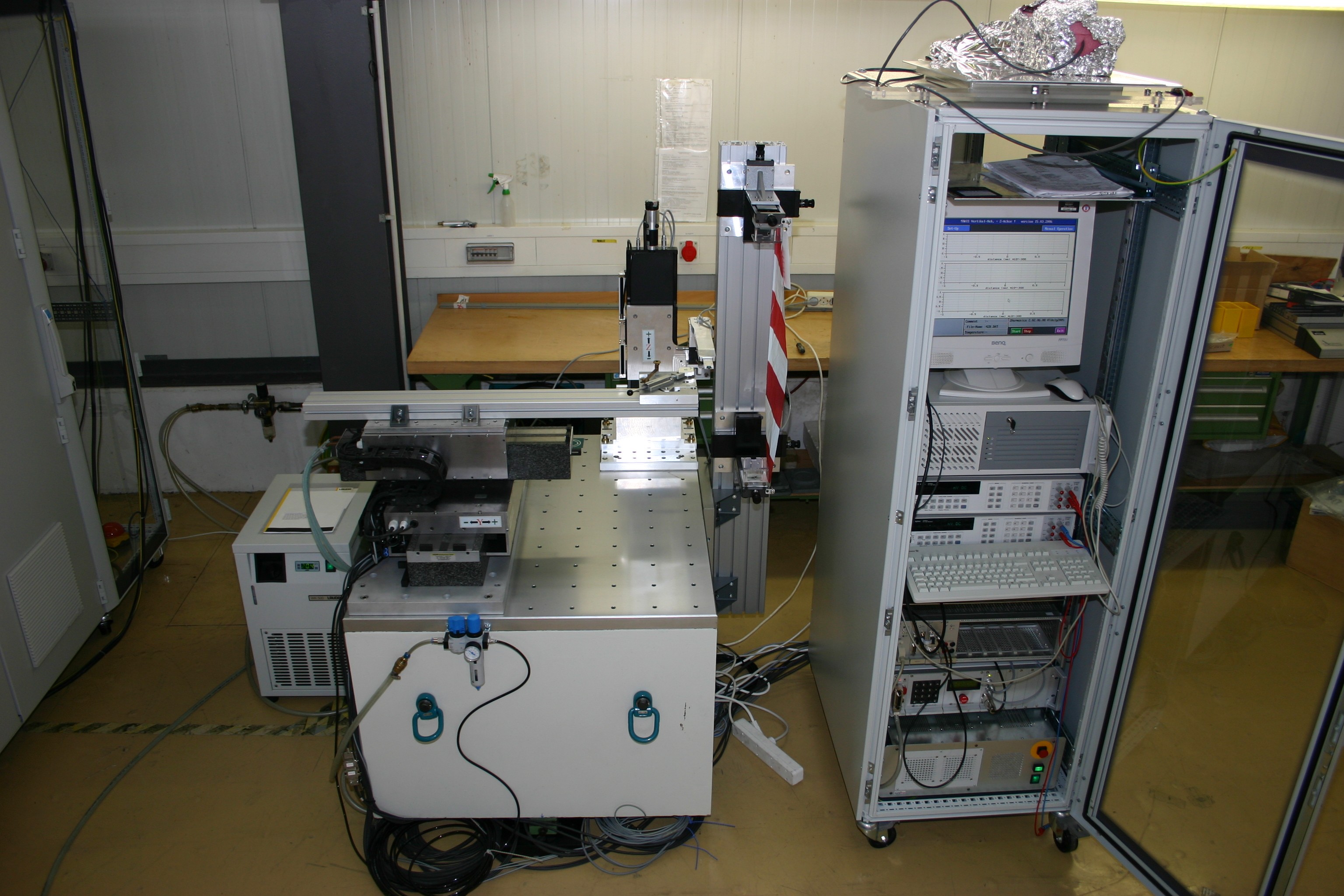
Stretched wire system for the characterization of magnet block inhomogeneities. By moving a magnetic block with respect to a stretched out wire (mimicking the electron beam) the induced voltage is representative for the integrated magnetic field.
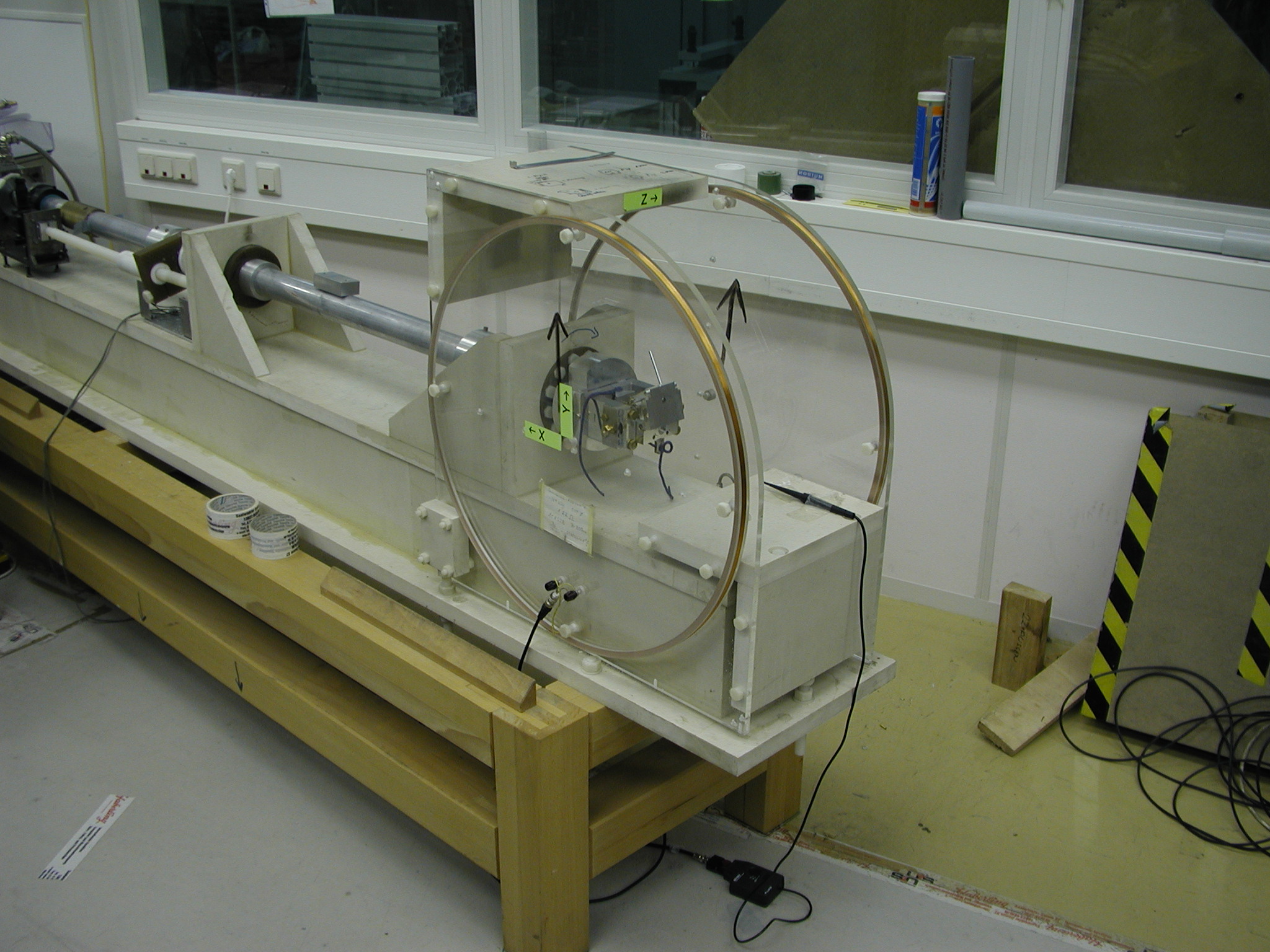
Automated Helmholtz coils system for the characterization of individual magnets with respect to their dipole moment. At the center of the coil there is a precision holder adapted to the geometry of the magnet to be measured which rotates around the horizontal axis perpendicular to the coil axis. The holder is rotated along two axes to obtain the dipole moment in the “xyz” directions. The data are corrected for speed variations and analyzed to yield the absolute value and the orientation of the dipole moment of the magnet.
To assure the constructive interference the gap must be the same within 20 µm all along the undulator. In order to allow the use of the 5th harmonic the reproducibility of gap and shift setting must be in the order of 1 µm. The gap and shift motion have to be realized in the presence of strong and variable magnetic forces reaching tons per meter undulator length. We achieve these specifications using an as stiff as possible support built around a cast iron structure designed by a bionic optimization procedure. The magnets are held in precision mounts bolted to the aluminum beams. The actual gaps and shifts are measured using optical encoders. High dynamical servo motors provide the motive force.
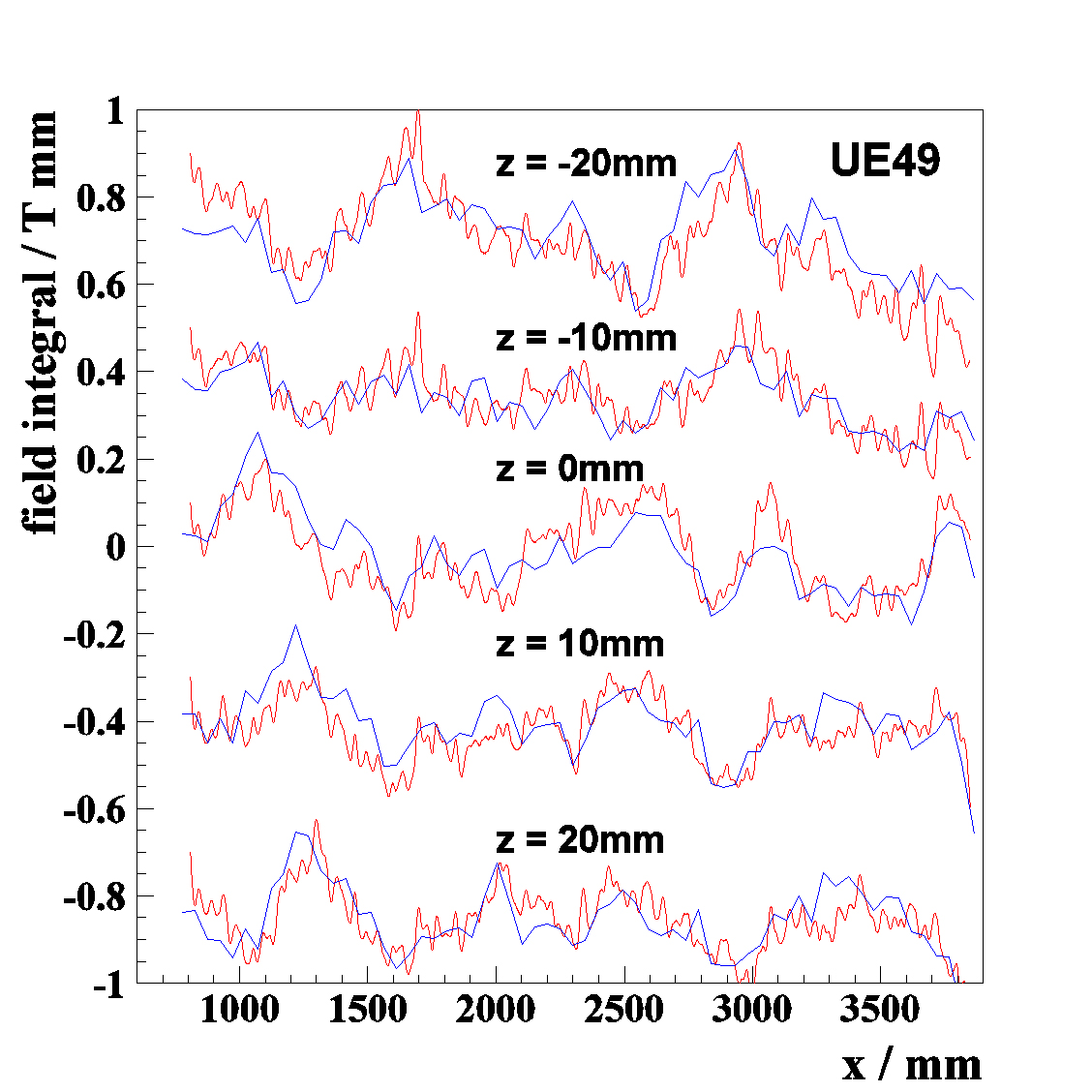
After assembly of an APPLE type undulator the typical remaining phase jitter is less than 4° for all operation modes i.e. the resonance condition is met from pole to pole within less than 1%. Furthermore, there is close agreement between the trajectories from magnetic measurements of the assembled undulator and those from previous magnetic measurements of the individual blocks. This unique result is caused by the high precision techniques developed at BESSY which are applied throughout the manufacturing process. At such a small phase jitter the brilliance is limited either by diffraction effects leading to transversely coherent beams, or by the finite emittance and energy spread of the electron beam. Thus, there is no need to further improve the magnetic field quality of BESSY undulators in this respect. Shimming is done only for the purpose of minimizing higher order multipoles.
Undulator shimming helps correct magnetic errors in undulators that cause beam trajectory issues, focusing effects, and other dynamic problems. Small pieces of permanent magnets or ferromagnetic materials (called shims) are strategically placed within the undulator to compensate for these errors. The effect of the shims depends on their size, position, and the magnetic field at their location. Shims in BESSY undulators also correct for shift-dependent effects and dynamic multipoles caused by edge focusing. This process improves beam stability and increases the dynamic aperture, leading to better beam lifetime and more efficient injection, which is crucial for the BESSY storage ring's operation.
Integrated magnetic field measurements
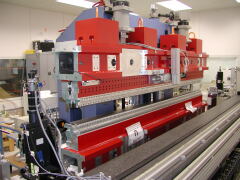
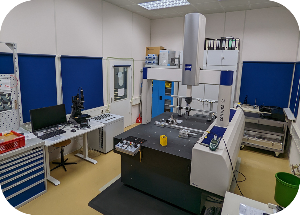
The group counts with a test bench for integrated magnetic measurements that consists of a slide on air cushions with a Hall probe located on a extender reaching the magnetic gap of the undulator. The system is also used to verify the mechanical straightness of assembled magnets. Additionally, a moving wire system is used to characterize the integrated multipoles with a high accuracy. It consists of two “xyz” positioning systems at either end of the undulator. A wire is stretched between them through the active volume of the undulator. The voltage induced in the wire is recorded. First and second field integrals are obtained as function of the transverse and vertical position inside the gap. The wire is also part of a pulsed wire set-up. Fig: UE46 Elliptical undulator at the bench for local and integrated magnetic field measurements.
Polarization characterization for BESSY II undulators is done using the BESSY Soft X-Ray Polarimeter. This tool uses two multilayer components: a transmission multilayer that acts as a polarizer and a reflecting multilayer as an analyzer. These components measure the linear polarization of the soft X-ray radiation. By adjusting the angles of these layers, the polarization is measured precisely. The Stokes parameters, which describe the polarization, are determined for different shifts of the undulator’s magnetic rows. The results match theoretical predictions, confirming that the soft X-ray radiation is fully polarized, with circular polarization for parallel shifts and linear polarization for anti-parallel shifts.