The BESSY Alternating Bunch Length Upgrade Proposal: BESSY-VSR
To address the increasing request for time resolved measurements, BESSY-VSR includes an innovative new scheme of longitudinal phase space manipulation. This scheme allows to generate simultaneously 15 ps (long) and 1.5 ps[1] (short) photon pulses, emitted by electron bunches of the same length [1,2]. In contrast to schemes discussed elsewhere like the usage of crab-cavities, these pulses are supplied to all dipole, undulator and wiggler beam lines. The transverse and longitudinal dimensions of the long bunches are similar to the excellent values supplied by the present user optics. This new operating mode will be achieved by installing a pair of strong longitudinally focusing superconducting (sc) rf-cavity system in the BESSY II ring operating in the present user optics. We plan to use one of the low-ß straight sections of the ring for the installation of these cavities, Fig. 1. A longitudinal focusing gradient (dV/dt) of a factor of 100 greater than possible with the present 500 MHz cavities seems to be feasible.
_________________
[1]rms values
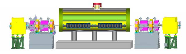
Figure 1: Scheme of a pair of sc rf cavity systems installed in one of the BESSY II straights.
For the technical realisation of BESSY-VSR the sc-cavities will operate at two different frequencies chosen such, that a beating of the rf-voltage is produced. One of the cavity systems operates at 1.5 GHz and 25 MV, the other one at 1.75 GHz and 21 MV. By this setup, two different types of buckets for electron storage exist at longitudinal positions located at the zero-crossings of the rf-voltage of both sc-cavities, spaced by 2 ns. For the first type, at each even bucket position, the voltage gradients cancel, here 15 ps long electron bunches are placed whose length are defined by the 500 MHz cavities. At the second type, at each odd bucket position, the voltage gradients add up and generate a strong, longitudinal bunch focusing, resulting in 1.5 ps short electron bunches, see Fig. 2. To relax the design of the active sc-cavities, they are only used for bunch focusing, whereas the energy loss by synchrotron radiation is recovered by the 500 MHz cavity.
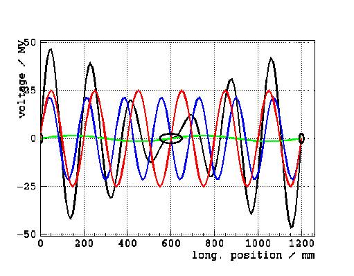
Figure 2: Voltage beating of the 3 cavity scheme. Voltages of the 0.5 GHz, 1.5 GHz and 1.75 GHz cavities are shown in green, red and blue, respectively, as a function of the relative longitudinal displacement from the reference particle. The resulting sum voltage is shown in black. Short bunches are placed at the longitudinal position 0 and 1200 mm, long bunches are placed at 600 mm, indicated by the black circles.
One of the concerns of the innovative BESSY-VS Rproposal are high current effects, related to the interaction of the stored beam with the sc rf-cavities, like the excitation of coupled bunch instabilities. These instabilities are presently under study. The BESSY-VSR proposal follows closely the BERLinPro project [3], where similar topics, like sc cavity design and interaction of high current beams with multi-cell cavities have to be addressed. From BERLinPro, a lot of expertise can be transferred to BESSY-VSR, including design and operation of cw sc cavities at 100-mA-level beam currents.
Short bunches of comparable length of 3 ps can be presently produced during dedicated beam shifts at BESSY in the low-a optics. However, the multi bunch current in this mode to produce stable (non-bursting) THz radiation is limited to 15 mA (only 40 mA single bunch currrent). At higher currents, bunches become unstable and emit bursts of THz radiation, a type of single bunch instability which degrades the bunch length and its energy spread, thereby affecting the quality of the photon spectra. The bursting current threshold is used as a figure of merit to characterize these bunches.

Figure 3: Schematic view of the bunch length-current relation. The bursting limit is given by the straight line. The present situation is given in red, the predicted BESSYVSR upgrading in blue, indicating the shift of the bursting threshold by a factor of 100 to higher currents.
As a rule of thumb, a current five times beyond the bursting threshold leads to a doubling of bunch length and energy spread, but not to beam loss. This lengthening effect was measured at BESSY II with a streak camera. The increase of the energy spread of bursting bunches is well visible at the MLS, where an increase of the energy spread up to a factor 5 was produced. For a given bunch length, the stable, non-bursting bunch current can be increased in proportion to the applied rf-gradient. This follows from simple scaling properties as predicted by theoretical models and confirmed by measurements, Fig. 3. This simple scaling is applied to predict the bursting threshold and the current in the short bunches, however, for short bunches less than 3 ps this scaling needs to be modified.
By applying strong longitudinal focusing in BESSY-VSR we expect an increase of the bursting threshold for the short bunch by a factor of 100 in current compared to the present low-a optics, i.e. short X-ray pulses of 100 times more intensity. Additionally, the short bunches emit extreme powerful THz radiation. For a fixed bunch shape, the intensity of the THz radiation growths with the square of the bunch current, yielding huge amounts of THz power.
The prediction of the achievable bunch length and the related bunch current, which can be stored in the short bunches, is presently subject of experimentally and theoretically studies at BESSY II and the MLS ring. Especially the MLS with its excellent low-a scheme is very well suited to explore short bunches.
The different bunches can be populated by electrons in various ways. Radiation protection limits the maximum average current to 300 mA. The long and short buckets are separated by 2 ns, defined by the 500 MHz cavity system. The long bunches are comparable in size to the present bunches, but needs to have twice the bunch charge, because there are only half as many bunches of this type. The long bunch filling will supply the normal user operation.
The upper multibunch current limit for the short bunches stored in the BESSY-VSR ring depends on impedance interaction with the machine, including the new multicell sc-cavities and the emitted THz power. The short bunches could damage the machine by impedance heating effects. This upper limit of several tens of mA can not be predicted easily. Whereas the bursting threshold of the 1.5 ps bunches is estimated by scaling relations to 0.8 mA per bunch.
The sc-cavities can be operated with a low-a optics as well to produce ultra short bunches of 300 fs and 4 mA multi bunch current, resp. 0.02 mA (16 pC) per bunch.
Three basic operation modes are being proposed by varying the bunch fill pattern, see Fig. 4, Fig. 5 and Fig. 6.

Figure 4: User optics with high flux and hybrid short pulses of 1.5 ps length: All long bunches outside the ion-clearing gap are populated to get an overall current of about 290 mA, some few short bunches inside the ion-clearing gap are populated with 0.8 mA per bunch. For time resolved measurements the separation between bunches of more than 2 ns would be an advantage.
- bunch laser slicing in combination with BESSY-VSR: At the slicing facility presently photon pulses of 50 fs (rms) are achieved. The slicing can be applied to few of the 1.5 ps bunches of BESSY-VSR, resulting in 10 times more charge and photon flux per slice.
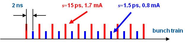
Figure 5: THz production mode: Short bunches of 1.5 ps are populated equally up to the impedance limit, the rest of the current up to 300 mA is filled into long bunches. The ion-clearing gap is left free. The short bunch current stays below the bursting limit to produce very stable THz radiation. Compared to the present low-a optics of 3 ps bunch length we expect about 200 times more THz power and with the only 1.5 ps long bunches one will get a 2 times broader THz spectrum up to 2 THz.

Figure 6: Ultra short bunches of 300 fs in the low-a optics: Operation of the sc-cavities in the low-a optics leads to ultra short bunches of 300 fs length at 0.02 mA (16 pC) per bunch. About 150 ultra short bunches can be filled in this way. The long bunches are similar in shape and current as produced by the present low-a optics. The BESSY II low-a optics is not a low-emittance optics, its value is about 5 times larger compared to the user optics because a relaxed transverse focusing is applied. If required, a low-emittance optics for this mode has to be developed.
As an extension of these schemes, the short and long bunches could be placed on different orbits and the user could choose at the beam port between transversally displaced short or long X-ray pulses. This could be done as a variation of the ALS (Berkeley) proposal to produce a pseudo single bunch for time resolved measurements, where one bunch of the filling is transversely kicked on a displaced orbit. More efficient would be a resonant kicking scheme, separating even and odd bunches transversely. Another possibility would be the technique of a double beam, presently developed at the MLS (and BESSY), where 150 mA beam current was stored on different orbits in a low-a optics. The different orbits where achieved by longitudinal a-buckets, a special tuning mode feasible in the low-a optics. In this mode the beam is stored in energetically displaced buckets on dispersive orbits. There is no pulsed element involved to kick the beam.
There are many open questions to be solved to get this scheme operational. The combined experience of the MLS with its advanced low-a tuning scheme and BESSY II provides unique tools to study the production and the properties of the short bunches.
[1] G. Wüstefeld, A. Jankowiak, J. Knobloch, M. Ries, Simultaneous Long and Short Electron Bunches in the BESSY II Storage Ring, Proceedings of the IPAC 2011, San Sebastian, Spain.
[2] M. Ruprecht et al., Single Particle Tracking for Simultaneous Long and Short Electron Bunches in the BESSY II Storage Ring, Proceedings of the IPAC 2013, Shanghai, China.
[3] J. Knobloch et al., Status of the BERLinPro Energy Recovery Linac Project, Proceedings of the IPAC 2012, New Orleans, USA.